

Multiplexer
A multiplexer is a combinational circuit that has ‘n’ input lines, ‘m’ selection lines and single output line. It is also known as many to one circuit. Multiplexer select binary information from many input lines and routes it to single output line. Its output is depending on value of select inputs or select lines.
For N input lines, m=log n (base2) selection lines, or we can say that for 2n input lines, m selection lines are required.

Table of Contents
8:1 Multiplexer
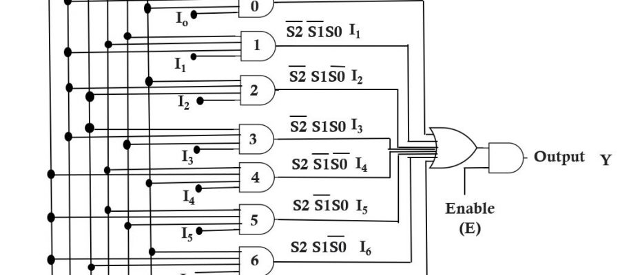
8:1 multiplexer circuit having 8 input lines I0, I1, I2…………..I7 , one enable input (E) , single output line (Y) and three select line (S0, S1,S2).


Select line calculate using given formula,
m=log n (base2)
where, n is the no. of input and m is the no. select line.
For 8:1 mux no. of select line
m=log2 23
m= 3 log2 2 (we know that log2 2 = 1 )
m=3
In 8:1 mux having 3 select lines. So, we can select any one of the input (depend on the value of select line) by moving the dialer we can have a input at the output. Dialer move and select input depend on the value of select line.
The one more input of multiplexer is Enable input (E). The function of Enable input is to enable the circuit it means, if E=1 (enable input is high) circuit operate and the output of the circuit is depends on the value of select line. If E=0 (enable input is low) circuit not operate and output of the multiplexer is zero its not depend on the value of select line.
The truth table of 8:1 mux


Operating Principle
When the enable input is 0, the output will be 0 irrespective of any input. With E=1,we can select any one of the eight inputs and connected it to the output. For example, if S2 S1 S0 = 101, then the data input I5 is selected and output Y will follow the input I5 .
Realization Using Logic Gate


Applications of an 8:1 multiplexer?
Please visit wiki here
Q1: What is an 8:1 multiplexer?
An 8:1 multiplexer, often referred to as an 8-to-1 multiplexer or simply an 8-input multiplexer, is a digital circuit component that selects one input signal from eight possible inputs and forwards it to a single output line based on control signals. It combines multiple input lines into a single output line.
Q2: What are the main features of an 8:1 multiplexer?
An 8:1 multiplexer typically consists of:
Eight input lines: These are the lines where the input signals are connected. Each line carries a separate input signal.
Three control lines: The number of control lines for an 8:1 multiplexer is three, enabling the selection of one input signal.
One output line: This line carries the selected input signal and transmits it as the output of the multiplexer.
Q3: How does an 8:1 multiplexer work?
The operation of an 8:1 multiplexer is based on the binary value applied to its control lines. The three control lines can take on eight different combinations of binary values (000, 001, 010, 011, 100, 101, 110, and 111). Each combination selects a specific input line, and the signal present on that line is forwarded to the output.
Q4: What are the applications of an 8:1 multiplexer?
Data selectors: The multiplexer can select one data input from multiple sources and route it to a data processing unit or output line.
Address decoding: In memory systems, an 8:1 multiplexer can assist in decoding an 8-bit address to select a specific memory location.
Bus routing: It can be used to route data or control signals from one of the eight sources to a bus or destination.