

There are many applications of microcontroller where we want to count external events such as generation of internal time delays between computer work and frequency of the pulse trains. This type of task is generally done by software techniques, but these software techniques will not give the exact result rather more important functions are not done.
To solve these problems timers and counters in the micro-controllers are best options for simple applications. In 8051 microcontroller, timers and counters are used as interrupts.
Read more topics related 8051 microcontroller : Click Here
Timers of 8051Microcontroller and their Registers
8051 Microcontroller has two 16-bit counters/timers: timer 0 and timer1. These timers work as a counter also. It means these timers perform dual function. When they work as a timer to generate a time delay or as counter to count events happening outside the microcontroller. Both timers are 16 bits wide.
We know that 8051 microcontrollers have an 8-bit microcontroller. So, it can process 8-bit data at a time. So, these registers are divided into two parts Higher 8-bits (TH) and Lower 8-bits (TL). The higher byte is stored in TH register and the lower byte is stored in TL register.
In short we can say that, timer is a special type of clock which is used to measure time intervals. Where as Counter is a device that able to count the number of times a particular event or process occurred, with respect to a clock signal. Counters can be easily implemented with the help of flip-flop.
Timer 0 Registers
Timer 0 register is 16 bits register and accessed as low byte and high byte. The TL0 is referred as a low byte register and the TH0 is referred as a high byte register. These registers can be also accessed like any other registers. Example, the instruction MOV TL0, #5H moves the value into the low-byte of Timer 0.


Timer1 Registers
Timer1 is also 16 bits register and is divided into two 8-bit register, referred to as TL1 (lower timer 1 register) and TH1 (Higher timer 1 register). The low byte register is referred as a TL0 and the high byte register is referred as TH0. These registers can be accessed like any other registers. Example, the instruction MOV TL1, #5H moves the value into the low-byte of Timer1.


During counter operation
- When these timer and counter act as a counter they always count Up. It starts counting from its initial value 0000 H and count up to FFFF H (max count value). Every time it will start counting it incremented by one.

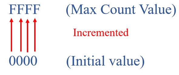
- After reaching its final value (FFFF H) if it counts again. It will return back to its initial value (0000 H). This condition is called Roll Over Condition.


- Maximum count rate of counter is 1/24 of the oscillator frequency.
- A counter can use an external signal to count the pulses.
TMODE & TCON Registers
Timers and counters in 8051 microcontrollers contain two special function registers: TMOD (Timer Mode Register) and TCON (Timer Control Register), which are used for selecting a mode of operation and controlling purpose.
TMODE (Timer Mode Control) Register:
TMODE register is used for selecting timer or counter mode of operation. It is an 8-bit register which is used by both timers 0 and 1 to set the various timer operation modes. The lower 4 bits are set for Timer 0 and the upper four bits are set for Timers1. In both cases, the upper 2 bits to specify the operation and the lower 2 bits are used to set the timer mode.

Gate: Bit D7 and D3 is allotted for gate. This bit is used to starting and stopping the timer. Timers can be started by software means and hardware means also. If the gate bit is set to ‘0’ this is the software way of starting and stopping the timer by an external source. If this bit is set to ‘1’ this is the software way of starting and stopping the timer.
C/T: Bit D6 and D2 is allotted for counter / Timer (C/T). This bit is used to decide whether a timer is used as a timer to generate time delay or used as a counter to work as a event counter. If this bit is set to be “0” then it is used as a timer to generate time delay and if it is “1” then it is used as a counter to external count event.
Mode selection Bits (M0 and M1): Bit D0, D1 and D4, D5 is allotted for M0 and M1 these are Mode selection Bits. The combination of these bits are used to select the timer mode.


Mode 1 (16-Bit Timer Mode)
Mode 1 is a 16-bit timer mode; It enabling them to count from 0000 to FFFFH and loaded into the timer’s registers TH and TL. The timer must be started after TH and TL are loaded with a 16-bit initial value. This can be done with the help of instructions “SETB TR0” for timer 0 and “SETB TR1” for timer 1. When rolls over condition will occurs It means it count from FFFF to 0000H, the TF (timer flag) flag bit is set to be high. If this roll over condition may occurs, we have option to stop the timer with the help of instructions “CLR TR0“ for timer 0 and CLR TR1 for timer. After the timer reaches its limit and rolls over condition occurs, again the process get repeat, the registers TH and TL must be reloaded with the original value and TF must be reset to 0.
Mode0 (13-Bit Timer Mode)
The operation of Mode 0 is exactly same like mode 1 except that it has a 13-bit timer instead of 16-bit in mode 1. The 13-bit counter can count values from 0000 to 1FFFH and loaded into the timer’s registers TH and TL. Therefore, every time timer is incremented by one, when the timer reaches its maximum value 1FFH, it rolls over to 0000, and TF (timer flag) flag bit is set to be high.
Mode 2 (8-bit Auto Reload mode)
This mode is an 8-bit auto reload mode. That allows the timer to load values of 00 to FFH into the timer’s register TH. After TH register is loaded with 8-bit value, the 8051 gives a copy of it to TL register. Then the timer must be started by using the instruction “SETB TR0” for timer 0 and “SETB TR1” for timer1. like mode 1.
After timer is started, it starts to count up by incrementing the value of TL register. It counts up until it reaches its final value of FFH. After reaching to its final value FFH if it again counts and reaches from FFH to 00H. This condition is called rolls over condition. It sets high the TF (timer flag). If using timer 0, TF0 goes high; if using TF1 then TF1 is raised. When Tl register rolls over from FFH to 00 and TF is set to 1, TL is reloaded automatically with the original value kept by the TH register. To repeat the process, we must clear TF register and without any need by the programmer to reload the original value. This makes mode 2 auto reload, whereas mode 1 in which programmer has to reload TH and TL.
Mode 3 (Split Timer Mode)
This mode is a split-timer mode, In this mode 16-bit timer is Split into two 8-bit timers i.e. THx and TLx like two 8-bit timer. In mode 0, 1 and 2, Timer 0 and 1 may be programmed independently. But mode 3 is different, here timers do not operate independently if mode 3 is chosen for timer 0. Placing timer 1 in mode 3 causes it to stop counting; the control bit TR1 and the timer 1 flag TF1 are then used by timer0.
TCON (Timer Control Register) Register
TCON is a register used to control operations of counters and timers in 8051 microcontrollers. It is an 8-bit register. The upper four bits are used for timers and counters operations and lower four bits are used for interrupts.


TF1: The bit 7 is allotted for Timer1 over flow flag bit. This bit is Set to 1 whenever timer rolls from all 1s to 0. And this bit is reset or cleared When the processor executes interrupt service routine (ISR) Located at program address 001Bh.
TR1: The bit 6 is allotted as a Timer 1 run control bit. This bit is Set to 1 by programmer to enable timer to count; It is reset or cleared to 0 by program to halt timer.
TF0: The bit 5 is allotted as a Timer 0 over flow flag. Same as TF1 (Timer1 over flow flag bit).
TR0: The bit 4 is allotted as a Timer 0 run control bit. Same as TR1 (Timer 1 run control bit).
IE1: The bit 3 is allotted as an External interrupt 1 Edge flag. It is not used in timer operations.
IT1: The bit 2 is allotted as a External interrupt1 signal type control bit. This bit is Set to be 1 by program to Enable the external interrupt 1 to be triggered by a falling edge signal. This bit is Set to be 0 by program to enable a low-level signal on external interrupt1 to generate an interrupt.
IE0: The bit 1 is allotted as an External interrupt 0 Edge flag. It is not used in to timer operations.
IT0: The bit 0 is allotted as an External interrupt 0 signal type control bit. Perform same function as IT1.
FAQ’S (Frequently asked questions)
What is difference between timer and counter in 8051?
8051 Microcontroller has two 16-bit counters/timers: timer 0 and timer1.This timer work as a counter also. It means these timers perform dual function. When they work as a timer they generate time delay or when they work as counter they count events happening outside the microcontroller. Both timers are 16 bits wide.
How many Timers & Counters connection does microcontroller have?
8051 Microcontroller has two 16-bit counters/timers: timer 0 and timer1. These timers work as a counter also. It means these timers perform dual function. When they work as a timer to generate a time delay or as counter to count events happening outside the microcontroller. Both timers are 16 bits wide.
We know that 8051 microcontrollers have an 8-bit microcontroller. So, it can process 8-bit data at a time. So, these registers are divided into two parts Higher 8-bits (TH) and Lower 8-bits (TL). The higher byte is stored in TH register and the lower byte is stored in TL register.
What are the modes of timers in 8051?
Timer Mode. In the timer mode, the internal machine cycles are counted.
Counter Mode.
TMOD Register.
Examples.
Mode 0 of Timer/Counter.
Mode 1 of Timer/Counter.
Mode 2 of Timer/Counter.
Mode 3 of Timer/Counter.
What are the applications of timer?
The timer is an important application in Embedded systems, it maintains the timing of an operation in sync with a system clock or an external clock. The timer has so many applications such as measure time generating delays, they can also be used for generating baud rates.
What is the function of mode 0 in 8051 timer?
The operation of Mode 0 is exactly same like mode 1 except that it has a 13-bit timer instead of 16-bit in mode 1. The 13-bit counter can count values from 0000 to 1FFFH and loaded into the timer’s registers TH and TL. Therefore, every time timer is incremented by one, when the timer reaches its maximum value 1FFH, it rolls over to 0000, and TF (timer flag) flag bit is set to be high.