

To monitors or control the various functions within a microcontroller like control different hardware peripherals like Timers, Serial Port, I/O Ports etc. Here we use some special registers in 8051 microcontroller called Special Function Register (SRF) (or Special Purpose Register, or simply Special Register).
If we want to assess or change the operating mode of the 8051 Microcontroller. This will be done by manipulating the 8051 Microcontroller Special Function Registers (SFRs).
In 8051 micro controller there are 21 Special function registers (SFR) and this includes Register A, Register B, Processor Status Word (PSW), PCON etc. So, it required 21 unique locations for these 21 special function registers and the size of each register is of 1 byte. Some of these special function registers are bit addressable registers (which means you can access 8 individual bits inside a single byte), while some others are only byte addressable register.4


Table of Contents
Registers in the 8051 Microcontroller
Registers are temporary storage locations inside any processor and a microcontroller that provide a fast way to store data and address of the memory location where the data is to be stored.
If you want to manipulate data within CPU of microcontroller by performing addition, subtraction, and so on, we cannot do that directly in the memory, but to do it you need some registers to process and store the data.
Microcontrollers contain several these types of registers that can be classified according to their content or instructions that operate in them.
Read More : Introduction 8051 Microcontroller,
Architecture of 8051 Microcontroller
More on 8051 Microcontroller click here
Types of Registers In 8051 Microcontroller
8051 microcontrollers mainly contain two types of registers:
- General-purpose registers (Byte addressable registers)
- Special function registers (Bit addressable registers)

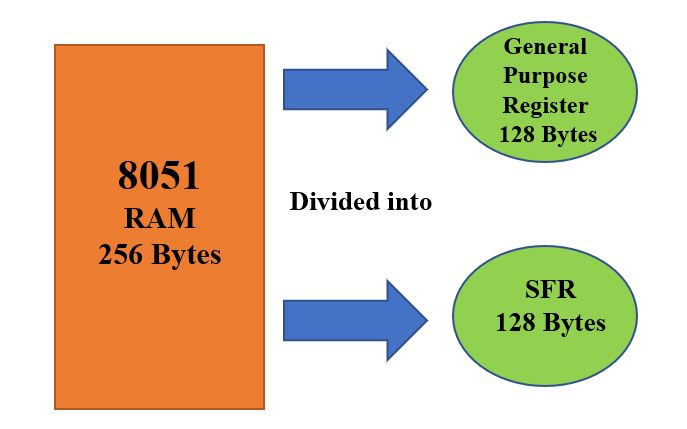
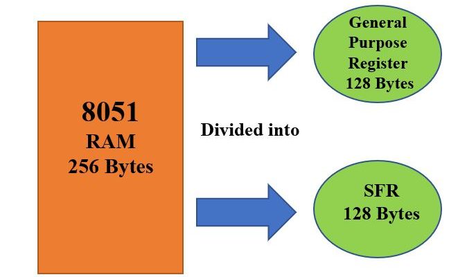
8051 microcontrollers basically consist of 256 bytes of RAM (Random Access Memory), which is divided into two parts, first part contain 128 bytes for general purpose Register these are byte addressable registers and second part contain 128 bytes for special function registers (SFR) memory these are bit addressable registers.
The part of memory which is used for general purpose is called as RAM, and the memory used for Special Function Register (SFR) contains all the peripheral related registers like Accumulator, ‘B’ register, Timers or Counters, and interrupt related registers.
General Purpose Registers
We know that a register is a storage element that can be store bits of information.
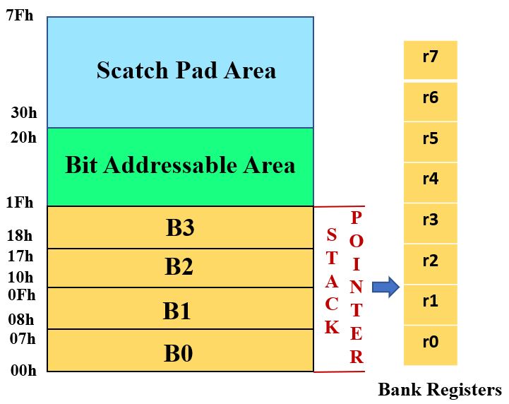
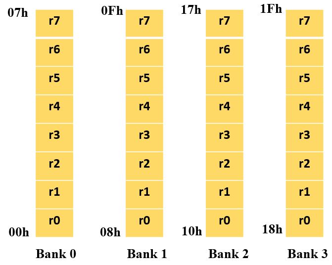
8051 microcontroller has 4 registers bank . These are B0, B1, B2, and B3 stand for Bank0, Bank1, Bank2, Bank3 respectively and each bank contains eight general purpose registers ranging from ‘R0’ to ‘R7’.
These are 32 general purpose registers address from 00h to 1Fh.
The address range of Register Bank 0 ( 00 h to 07 h)
The address range of Register Bank 1 ( 08 h to F h)
The address range of Register Bank 2 ( 10 h to 17 h)
The address range of Register Bank 3 ( 18 h to 1F h)
These Register Banks are selected with the help of PSW (Program Status Word)Register bits i.e. RS0, RS1.


Special Function Registers (SFR’s)
In 8051 micro controller there are 21 Special function registers (SFR) and this includes Register A, Register B, Processor Status Word (PSW), PCON etc etc. There are 21 unique locations for these 21 special function registers and each of these register is of 1 byte size.
The 21 SFR of 8051 Microcontroller are categorized into seven groups these are:
- Math or CPU Registers: A and B Register
- Status Register: PSW (Program Status Word) Register
- Pointer Registers: DPTR (Data Pointer – DPL, DPH) and SP (Stack Pointer) Registers
- I/O Port Latches: P0 (Port 0), P1 (Port 1), P2 (Port 2) and P3 (Port 3) Registers
- Peripheral Control Registers: PCON, SCON, TCON, TMOD, IE and IP Registers
- Peripheral Data Registers: TL0, TH0, TL1, TH1 and SBUF Registers
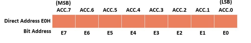
Accumulator (A register):
- It is an 8-bit register.
- It holds a data and receives the result of the arithmetic instructions.
- ACC is usually accessed by direct addressing and its physical address is E0H. Accumulator is both byte and bit addressable. if you want to access the second bit (i.e bit 1), you may use E1H and for third bit E2H and so on.

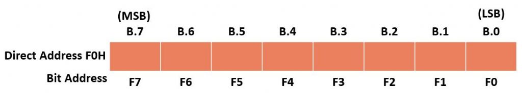
B Register:
- It is 8-bit register.
- It is bit and byte-addressable register.
- You can access 1-bit or all 8-bits by a physical address F0h. Suppose to access a bit 1, we have to use f1.
- The B register is only used for multiplication and division arithmetic operations.

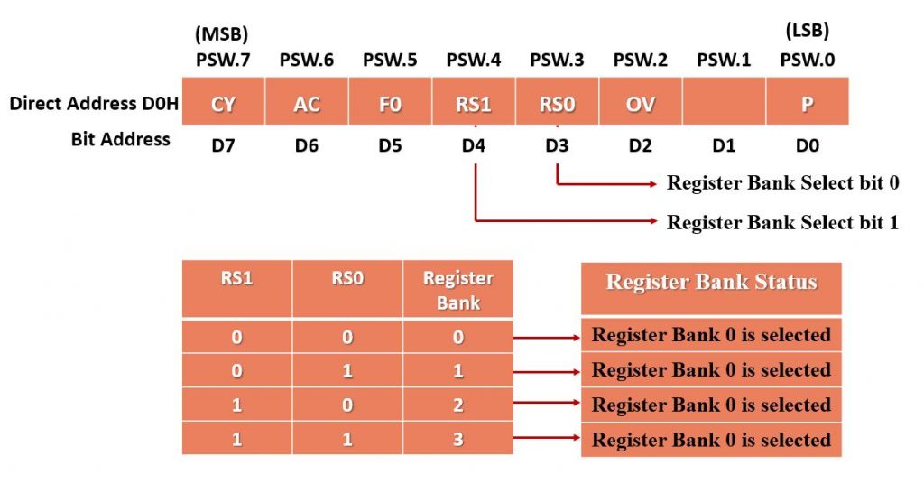
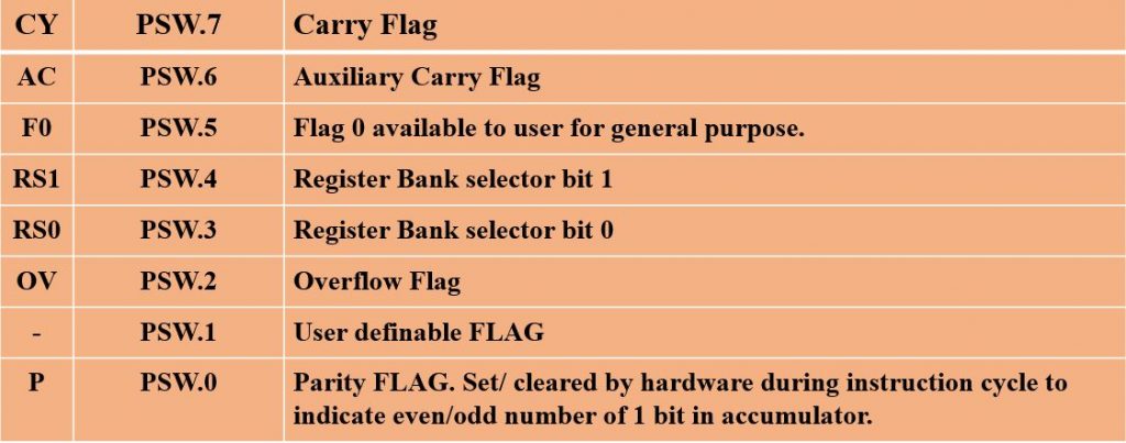
PSW (Program Status Word) Register:
The PSW (Program Status Word) Register is also called as Flag Register. It is one of the important SFRs in 8051 microcontrollers. It is also an 8-bit register. It consists of Flag Bits or status bits that reflect the current state of the CPU. This will help the programmer in checking the condition of the result and also make decisions.
PSW flag register is both bit and byte addressable. The physical address of PSW starts from D0H. The individual bits are accessed by using bit address D1, D2 … D7. The two unused bits are user-defined flags. Four of the flags are called conditional flags, which means that they indicate a condition which results after an instruction is executed. These four are CY (Carry), AC (auxiliary carry), P (parity), and OV (overflow).


Timer/Counter Registers:
- The 8051 has two 16-bit Programmable timers / counters (Timer 0 – Timer 1).
- Which can be used either as timer to generate a time delay or as counter to count events happening outside the microcontroller.
- The Counters and Timers in 8051 microcontrollers contain two special function registers: TMOD (Timer Mode Register) and TCON (Timer Control Register).
TMODE Registers:
- TMODE register is an 8-bit register.


- Gate: when Gate control is set. Timer/counter is enable only while the INTx pin is high and the TRx control pin is set. When it is cleared, the timer is enabled whenever the TRx control bit is set.
- C/T: The Timer or counter selection. When cleared for timer operation (input from internal system clock). Set for counter operation (input from Tx input pin).
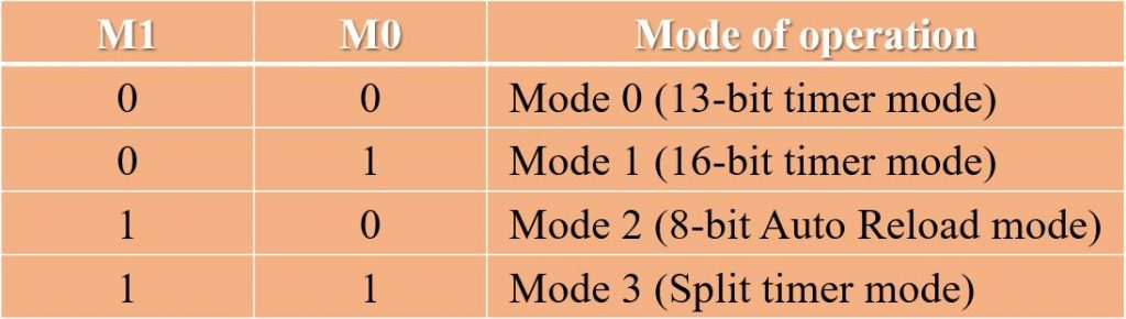
- Mode selects bits of TMODE register: The M1 and M0 are mode select bits, which are used to select the timer operations. There are four modes to operate the timers.

TCON Registers:
- It is Timer control Register.
- It is an 8-bit register.


SP (Stack Pointer)
- The stack is a portion of a RAM Used by the CPU to store data or memory address on temporary basis.
- The stack pointer register is used to access the stack is known as SP register. The stack pointer register is 8-bits wide. It can take a value of 00 to FFH. The RAM memory location 08H is the first location used for the stack. When the 8051 microcontroller is initialized, the SP register contains the value 07H.
- If we want to store CPU register data into the stack this is known as PUSH operation and if we getting the data from stack back into a CPU register this is known as a POP operation.


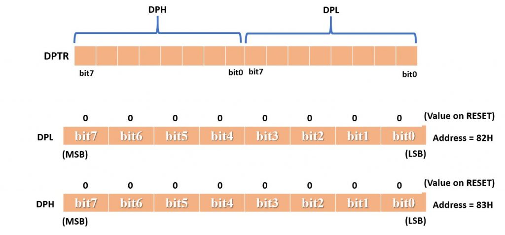
DP (Data pointer register):
- The data pointer is a 16-bit register used to hold the 16-bit address of data memory. This can also be used as two 8-bit register namely DPH and DPL. Data Pointer can be used as a single 16-bit register (as DPTR) or two 8-bit registers (as DPL and DPH).
- The 8-bit data pointers are used for accessing internal RAM and SFR. The 16-bit data pointer is used for accessing external data memory.
- The contents of data pointer are programmable using instructions. It is used by the 8051 to access external memory using the address indicated by DPTR.

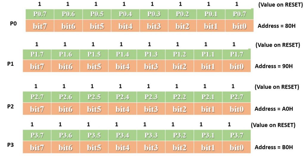
Port Registers:
8051 microcontrollers have 4 bidirectional I/O ports. Port 0, Port 1, Port 2 and Port 3 (P0, P1, P2 and P3). Which can be work as input or output port. Each port having 8-bits. Hence, total 32 input/output pins allow the microcontroller to communicate with outside world means this port allow to be connected with the peripheral devices.

PC (program Counter):
It is a 16-bit register. It is use to hold the address of the memory location from where the next instruction to be fetched.
when the 8051 initializes PC starts at 0000h and it is automatically is incremented every time after an instruction is executed. (So in this way PC maintain the sequence of program execution).
Due to this the width of the PC decides the max program length in bytes.
wiki link
Mam please microcontroller ka MCQ question video bna digiye total kyuki 22 July se exam hai online