

In this article, we will discuss about some basics, operation (using circuit diagram) and waveform of single-phase full bridge inverter with resistive load. Here we also discuss the Comparison between half and full bridge inverters.
What is a Full Bridge Inverter?
Single Phase Full Bridge Inverter is basically a voltage source inverter and it is a topology of H-bridge inverter used for converting DC power into AC power.
In case of Single Phase Half Bridge Inverter, we require three wire DC input supply. Where as in Single Phase full Bridge Inverter we use two wire DC input supply, which suffices the requirement. By controlling the turn ON and turn OFF time of the thyristor output frequency can be easily controlled.
Single phase full bridge inverter circuit required more component for conversion than that used in single phase Half bridge inverters so, the cost of the circuit get increases.
The full bridge inverter circuit basically consists of 4 feedback diodes and 4 controlled switches (like Thyristor, IGBT or MOSFET).
Single Phase Half Bridge Inverter R load
Single phase Half Bridge Inverter circuit basically consist of four Thyristor (T1to T4) and four diode (D1to D4) these diodes are called feedback diode and these diodes function only when the load is other than Resistive Load. Each diode is connected in anti-parallel with each thyristor.

A voltage source and a resistive load. Here load is connected between two points A and B. The output current direction is considered as positive when current flow from A to B and output voltage is considered as positive when A is positive w.r.t. B.
Operation Of Single-Phase Half Bridge Inverter R load
The operation of Single-Phase Half Bridge Inverter R load is based on the sequential triggering of thyristors placed diagonally opposite. This means that only two thyristors are turned ON in half of the time period like thyristors T3 & T4 will be triggered while for the remaining half of time period, T1 & T2 will be triggered.
Now, the operation of Half Bridge Inverter is divided into two modes.
Mode – 1: 0 < t < T/2
Mode – 2: T/2 < t < T
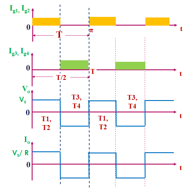
Mode I (0 < t < T/2): In this mode we give gate triggering pulse to thyristor T1 and T2. So, T1 and T2 get turned on. So current flow from Supply Vs…. T1……load…. T2…back to Vs. This time the direction of current flow across load is positive because point A is positive w.r.t. point B.
This time output voltage is also positive Vo = Vs.
The output current is Io = Vs/RL
Mode II (T/2 < t < T): In this mode we give gate triggering pulse to thyristor T3 and T4. This time T3 and T4 get turned on and thyristor T1 and T2 get turned off. So current flow from Supply Vs…. T3……load…. T4…back to Vs. This time the direction of current flow across load is negative because point B is positive w.r.t. point A.
This time output voltage is also negative Vo = (-Vs).
The output current is Io = – Vs/RL
Here we see in the waveform, if load is pure resistive the output voltage and output current waveform is identical (same).
Now, we draw the waveform

Analysis Of Full Bridge Inverter Resistive Load


What is the purpose of diodes in full Bridge Inverter circuit?
In full bridge inverter circuit if the load is purely resistive, there is no need to connect diodes D1 to D4 in a circuit because in case of resistive load both output voltage and current are always in phase with each other.
But if loads are not a purely resistive load, then the output current (io) will not be in phase with the output voltage (Vo). In such case, the diodes D1 to D4 connected in anti-parallel with the thyristors T1 to T4 respectively. This will allow the flow of current when main thyristor is turned off. These diodes (D1 to D4) are called feedback diode . Because when these diode conducts, the energy is fed back to the DC source.
Comparison between Half & Full Bridge Inverters:
| Half Bridge Inverter | Full Bridge Inverter |
| It consist of two thyristors and two feedback diodes. | It consists of four thyristors and four flyback diodes. |
| The circuit cost of half bridge inverter is less as compare to full bridge inverter circuit because it required less components. | The circuit cost of full bridge inverter is high as compare to half bridge inverter circuit because it required large no of components. |
| The magnitude of output voltage is half of the magnitude of input DC source. | The magnitude of load voltage is equal to the magnitude of DC input source. |
| Half bridge inverter use three wire DC input supply. | The drawback of half bridge inverter is overcome by full bridge inverter because it requires two wire DC source. |
| The output power of half bridge inverter is less than full bridge inverter. | The output power of full bridge inverter is four times that of for half bridge inverter. |
Frequently asked questions (FAQ’s)
What is the major difference between full bridge inverter and half bridge inverter ?
The major difference between the single phase half and full bridge inverter is that former requires a three wire DC input source while the latter requires two wire DC source.
What is the advantage of full bridge inverter?
The output power of full bridge inverter is four times that of for half bridge inverter.
What is drawback of full bridge inverter?
three major disadvantages:
i) Two electrolytic capacitors connected in series are needed at the dc input side.
ii) It is unable to generate zero output voltage intervals for non-resistive loads.
iii) The amplitude of the output voltage pulses is half of the dc input voltage.
What does a full bridge inverter do?
A full bridge single phase inverter is a switching device that generates a square wave AC output voltage on the application of DC input by adjusting the switch turning ON and OFF based on the appropriate switching sequence, where the output voltage generated is of the form +Vdc, -Vdc, Or 0.