Three phase Inverter convert a DC voltage into three phase AC voltage. In industrial application three phase inverter are more commonly used than single phase inverter. Such as three phase inverters are basically used for variable-frequency drive applications and for high power applications (like HVDC power transmission).
Three phase inverters basically consists of three single-phase inverter switches each connected to one of the three load terminals.
A three phase inverter is also known as six-step bridge inverter. Here, step is defined as a Switching sequence of SCR or firing from one SCR to the next SCR in a sequence. For getting one complete cycle of 360°, each step is of 60-degree interval. This means, thyristors will be turned on at a regular interval of 60-degree in a sequence. So, that three phase AC output voltage is synthesized at its output.
To achieve high voltage, current and power ratings inverter, two three phase six inverter can be connected in series for higher voltage rating and two three phase six inverter can be connected in parallel for higher current rating. In both the cases, the output waveforms are 12-step waveform.
Classification of Three Phase Inverter :
Three Phase Inverter are classified in two types:
- 180-degree conduction mode
- 120-degree conduction mode
The circuit diagram for both the conduction modes are same.
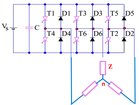
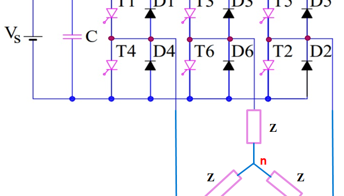
Circuit Diagram of Three Phase Bridge Inverter:
The circuit diagram of three phase bridge inverter consists of minimum of 6 SCR and 6 diodes. Here a large capacitor is connected at the input side in parallel with Vs to make input DC voltage constant. This capacitor reduces the harmonics feedback to the source. The three-phase inverter is assumed to be star connected.