

A multiplexer is a combinational circuit that has ‘n’ input lines, ‘m’ selection lines and single output line. It is also known as many to one circuit. Multiplexer select binary information from many input lines and routes it to single output line. Its output is depending on value of select inputs or select lines.

For N input lines, m=log n (base2) selection lines, or we can say that for 2n input lines, m selection lines are required.
The multiplexer, abbreviation to “MUX”.
Multiplexers work as a Data selector circuit”. It selects data from many input lines and routes it to the single output line.
Table of Contents


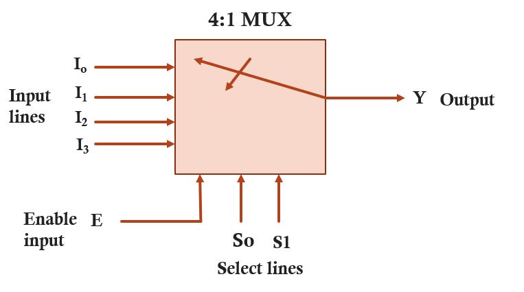
The above diagram is a multiplexer circuit having 4 input lines, one enable input , single output line and 2 select line. Select line we calculate using m=log n (base2) formula, where n is the no. of input and m is the select line. We can select any one of the input by moving the dialer we can have a input at the output. Dialer move and select input depend on the value of select line.
Multiplexer Is available in the form of IC (integrated circuit). It is a MSI (medium scale integrated circuit ). For different multiplexer circuits different IC’s are available. We can implement various combinational circuits using multiplexer IC like half adder, full adder, Subtractor etc.
Half Adder Read More
Full Adder Read More
Advantage of Multiplexer
- It reduces the number of wires.
- Hence, it reduces the circuit complexity, cost and size.
- We can implement many combinational circuits using MUX.
- It simplifies the logic design.
It does not need the k-maps and simplification.
Classification of Multiplexer
Multiplexer may be classified as under:
- 2:1 Multiplexer
- 4:1 Multiplexer
- 8:1 Multiplexer
- 16:1 Multiplexer
2:1 Multiplexer
The block diagram of 2:1 multiplexer has been shown in figure. It has two data inputs Io and I1 , one select input line (S), enable input (E) and one output. The output of the circuit is depends on the value of select line. The truth table of 2:1 mux has been shown below.


From the above truth table, we enable input E=1 circuit operate and we get the output
Therefore, The logical expression for output Y is as follows:
Y= ES’Io + ESI1 or Y = E(S’Io + SI1)
Using the above logical expression, do realization using gates


Multiplexer work as a switch
A multiplexer can be considered as a digital switch. It selects one input from multiple sources and routes it to the output. In this sense, the terms “multiplexer” and “switch” are sometimes used interchangeably.
Multiplexer in detail click here
8:1 Multiplexer in detail click here
for more detail check in wiki
Q1: What is a multiplexer?
A multiplexer, often abbreviated as MUX, is a digital electronic device that allows the selection of one of several input signals and forwards it to a single output line. It combines multiple input lines into a single output line based on control signals.
Q2: What are the main components of a multiplexer?
A multiplexer consists of three primary components:
Input lines: These are the lines where the input signals are connected. The number of input lines in a multiplexer is determined by its configuration, such as 2-to-1, 4-to-1, 8-to-1, etc.
Control lines: These lines determine which input signal is selected and passed to the output. The number of control lines depends on the number of input lines in the multiplexer.
Output line: This is the line where the selected input signal is transmitted.
Q3: What are the common applications of multiplexers?
Multiplexers are widely used in digital systems for various purposes, including:
Data transmission: Multiplexers can combine multiple data streams into a single transmission line, optimizing bandwidth and reducing the number of required connections.
Address decoding: Multiplexers are used to select specific memory locations by decoding binary address inputs.
Logic circuit implementation: They can be utilized to implement logical functions, such as AND, OR, and XOR gates, by appropriately configuring the input and control lines.
Analog-to-digital conversion: Multiplexers are employed in analog-to-digital converters (ADCs) to select different analog input channels for conversion.
Q4: How does a multiplexer work?
The working principle of a multiplexer is relatively straightforward. The control lines determine which input line is selected and forwarded to the output. For instance, in a 4-to-1 multiplexer, there are two control lines, allowing the selection of one of the four input lines. The binary value applied to the control lines determines which input is chosen.
Q5: What is the difference between a multiplexer and a demultiplexer?
While multiplexers select one input from multiple sources and direct it to a single output, demultiplexers perform the opposite function. Demultiplexers take a single input line and distribute it to one of several output lines based on control signals.
Q6: What is the relationship between a multiplexer and a switch?
A multiplexer can be considered as a digital switch. It selects one input from multiple sources and routes it to the output. In this sense, the terms “multiplexer” and “switch” are sometimes used interchangeably.
Q8: What are there different types of multiplexers?
multiplexers come in various configurations, typically defined by the number of inputs and control lines. Some common types include 2-to-1, 4-to-1, 8-to-1, and 16-to-1 multiplexers.