

Introduction Multiplexer
A 4: 1 multiplexer is a combinational circuit that has ‘n’ input lines, ‘m’ selection lines and single output line. It is also known as many to one circuit. Multiplexer select binary information from many input lines and routes it to single output line. Its output is depending on value of select inputs or select lines.
For N input lines, m=log n (base2) selection lines, or we can say that for 2n input lines, m selection lines are required.
Table of Contents

Multiplexer in detail click here
8:1 Multiplexer in detail click here
4:1 Multiplexer


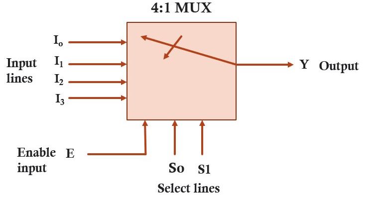
4:1 multiplexer circuit having 4 input lines I0, I1, I2 and I3 , one enable input (E) , single output line (Y) and 2 select line (S0, S1).
Select line calculate using given formula, m=log n (base2)
where n is the no. of input and m is the no. select line.
For 4:1 mux no. of select line
m=log2 22 (22 =4)
m= 2 log2 2 (we know that log2 2 = 1 )
m=2
In 4:1 mux having 2 select lines. So, we can select any one of the input (depend on the value of select line) by moving the dialer we can have a input at the output. Dialer move and select input depend on the value of select line.
The function of Enable input is to enable the circuit it means if E=1 (enable input is high) circuit operate and the output of the circuit is depends on the value of select line. If E=0 (enable input is low) circuit not operate and output of the multiplexer is zero its not depend on the value of select line.
Block Diagram of 4:1 Multiplexer

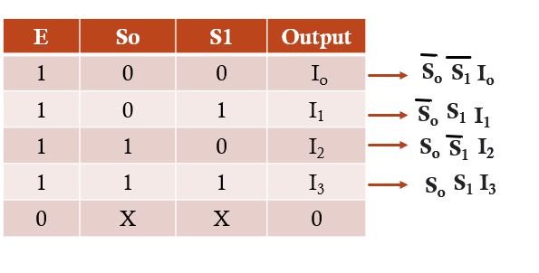
Truth Table of 4:1 Multiplexer


The above truth table tell us that if select lines value S0S1 = 00, Input I0 is select and routed to output
Therefore, we have Y=I0 when S0S1 = 00
Similarly, if select lines value S0S1 = 01, Input I1 is select and routed to output
Therefore, we have Y=I1 when S0S1 = 01
Similarly, if select lines value S0S1 = 10, Input I2 is select and routed to output
Therefore, we have Y=I2 when S0S1 = 10
Similarly, if select lines value S0S1 = 11, Input I3 is select and routed to output
Therefore, we have Y=I3 when S0S1 = 11

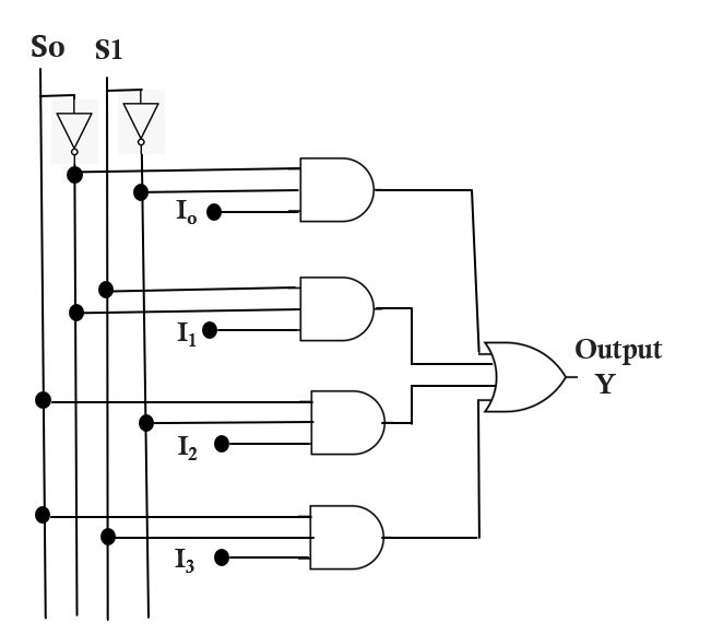
From truth we get the logical expression for output Y in the SOP form will be as under
Y= S’0 S’1 I0 + S’0 S1 I1 + S0 S’1 I2 +S0 S1 I3
Using the above logical expression, do realization of 4:1 mux using basics logic gates

Wikilink here