


An inverter, is a power electronics device which used to convert fixed DC (Direct Current) into controlled AC (Alternating Current)”. Here, Controlled AC means we controlled two parameter of AC signal Frequency and Amplitude.
In other words, the inverter is a static device. It can convert one form of electrical energy into other forms of electrical energy. But it cannot generate electrical power.
Inverter takes DC power from the batteries and converts into AC power at the time of the power failure.
In inverter we use some power semiconductor switching devices like IGBT, MOSFET, GTO because these devices having self-commutation property.
A power inverter convert bulk DC power into AC power and used in the power system network. For example power inverters are used at the receiving end of HVDC transmission lines. This inverter is known as a grid-tie inverter.
Who Invent the Inverter?
Before inverter, DC (Direct Current) to AC (Alternating Current) conversion is done with the help of a motor-generator set and rotary converter. The term inverter was first introduced by David Prince titled “The Inverter” in 1925. Prince defined the inverter as the “Inverse of a Rectifier”.
Working Principle of Inverter
The basics function of inverter is to convert DC power into AC power, while at the same time regulating the voltage, current and frequency of the signal. Basically, Inverter is a kind of oscillator.
- Transistors are the key components of inverter, which convert DC power into AC power.
- IGBT, MOSFET are the most commonly used switches in inverter.
- How many numbers of switches we use depends on the type of inverter?
- The transistor is used to change the steady voltage and one-way current flow of DC to the constantly changing voltage and oscillating current of AC.
- The key feature of the transistor in the generation of AC power is that it can rapidly switched on or off.
More on inverters
Three Phase Inverter: it’s Basics and circuit diagram
Parallel Inverter: It’s Basics, Operation and waveform
Series Inverter: It’s working, Operation and Waveform
Single Phase full Bridge Inverter – RL Load
Single Phase Full Bridge Inverter – Resistive Load
Difference between Inverters VSI vs CSI
Let’s see the working:
Here we see in the circuit diagram here we use 12V battery, one transformer (Primary winding of transformer is Center tapped), One two-way switch and 50 Hz oscillator.

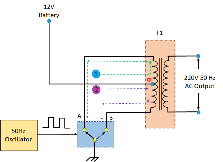
Here 12V battery generate DC supply and inverter will change it into, AC supply of 220V, 50Hz to use to operate any appliances.
The 12V DC supply from the positive terminal of the battery comes to the primary winding of transformer which is center tapped. The two ends of the primary winding of transformer (A and B point) are connected to the two-ways switch to the ground. If the switch connects to A point of the primary winding. The current flows from the battery into upper half of primary winding (o) through A contact of th e switch to the ground. If switch turn from A point into B point. This time the current number 1 stops flowing. Then, the current 2 flows to the ground through o and contact B of the switch.
Here, 2 ways switch is controlled with the square wave oscillator it generates a frequency of 50 Hz. It causes the switch to selects between A and B point with speed about 50 times per second. Also, the current 1 and 2 flows to the transformer alternately at a rate of 50 times per second. So, the current flows into the transformer alternately look like AC voltage.
We know that transformers work on the principle of Electromagnetic induction. When current flow in primary winding EMF induced and a current will be induced into the secondary winding of transformer. Which it causes AC voltage 220V 50Hz. Now, the voltage is use to be supplied to the various types of electrical equipment that operate in 220 Volt AC supply.
Applications Of Inverter
- When the AC main power supply is not available, an uninterruptible power supply (UPS) uses battery and inverter.
- Power inverters are basically, used in the HVDC transmission line. It also used to connect two asynchronous AC systems.
- The output of the solar panel is DC power. The solar inverter used to convert DC power into AC power.
wiki link
FAQ’s (Frequently Asked Questions)
What is inverter?
An inverter, is a power electronics device which used to convert fixed DC (Direct Current) into controlled AC (Alternating Current)”. Here, Controlled AC means we controlled two parameter of AC signal Frequency and Amplitude.
When we use inverter?
At the time of the power failure or power cutoff inverter takes DC power from the batteries and converts into AC power.
What is power inverter?
A power inverter convert bulk DC power into AC power and used in the power system network. For example power inverters are used at the receiving end of HVDC transmission lines. This inverter is known as a grid-tie inverter.
Who Invent the Inverter?
Before inverter, DC (Direct Current) to AC (Alternating Current) conversion is done with the help of a motor-generator set and rotary converter. The term inverter was first introduced by David Prince titled “The Inverter” in 1925. Prince defined the inverter as the “Inverse of a Rectifier”.
What is kVA inverter?
UPS systems are often “sized” by a kW (kilowatts) and/or a kVA (kilo-volt-amperes) rating. For example, a 1 kVA UPS means its circuitry can handle 1,000 volt-amperes. For example, 1kVA UPS from N1C has the capacity to power 900 watts of connected equipment. This means the UPS has a “power factor” of 0.9.