

Inverter is an electronic circuit which converts DC power into AC power. The inverter circuit in which the commutating component C (capacitor) is connected in parallel with the load via transformer called a parallel inverter. This circuit is also called Push-pull inverter.
Parallel Inverter working is similar to the class B commutation. Parallel inverter has important role in Uninterrupted Power Supply (UPS).
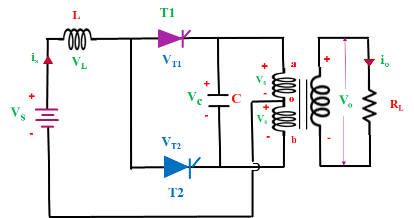
Parallel inverter circuit consist of two thyristor T1 and T2, a transformer, inductor L and a commutating component C. Capacitor (C) is connected in parallel with the load via transformer therefore it is called a parallel inverter. And inductor (L) is connected in series with supply to make the source current constant. Here we also use a center -tapped transformer. Centre tapping is done in the primary winding of transformer so, primary winding is divided into two equal halves ao and ob.

Operation of Parallel Inverter:
The operation is divided into four modes:
Mode I (0< t < t1): In this mode we give firing pulse to thyristor T1 and T1 get turned on and T2 is turned off. Current flow from Supply Vs …. T1…. ao (upper half of primary winding) …. back to Vs. As a result, Vs voltage is induced across upper as well as lower half of the primary winding of transformer. And Vs voltage is induced in secondary winding.

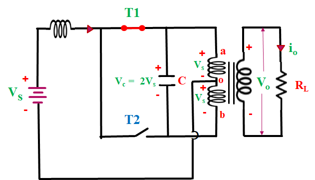
So, output voltage across load is Vs.
So, the total voltage across primary winding is 2Vs. Here capacitor is connected in parallel with primary winding therefore capacitor charge with 2Vs voltage with upper plate is positive and lower plate is negative.
Mode II (t1< t < t3): In this duration we give firing pulse to thyristor T2 and T2 get turned on. At this time capacitor start discharging through T1 therefore T1 turned OFF. This time current flow from supply Vs …. T2…. bo (lower half of primary winding) …. back to Vs.
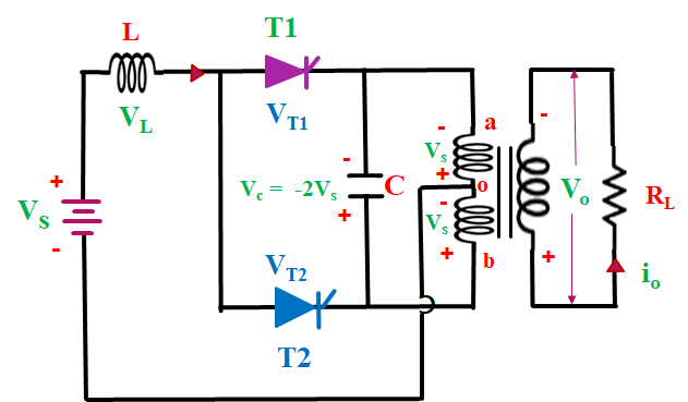
Now this time capacitor charged with upper plate is negative, from +2Vs at t=t1 to -2Vs at t=t2. Load voltage also changes from Vs at t=t1 to -Vs at t=t2. After t=t2 voltage across capacitor is maintain constant -2Vs between t= t2 to t3.
So, load voltage is also constant -Vs.
Mode III (t3< t < t4): In this mode again, we give firing pulse to thyristor T1 and T1 get turned on. At this time capacitor start discharging through T2 therefore T2 turned OFF. This time current flow from supply Vs …. T1…. ao (upper half of primary winding) …. back to Vs. So, the total voltage across primary winding is 2Vs.

Now this time capacitor charged with upper plate is positive, from -2Vs at t=t3 to +2Vs at t=t4. Load voltage also changes from Vs at t=t3 to -Vs at t=t4.
So, output voltage across load is Vs.
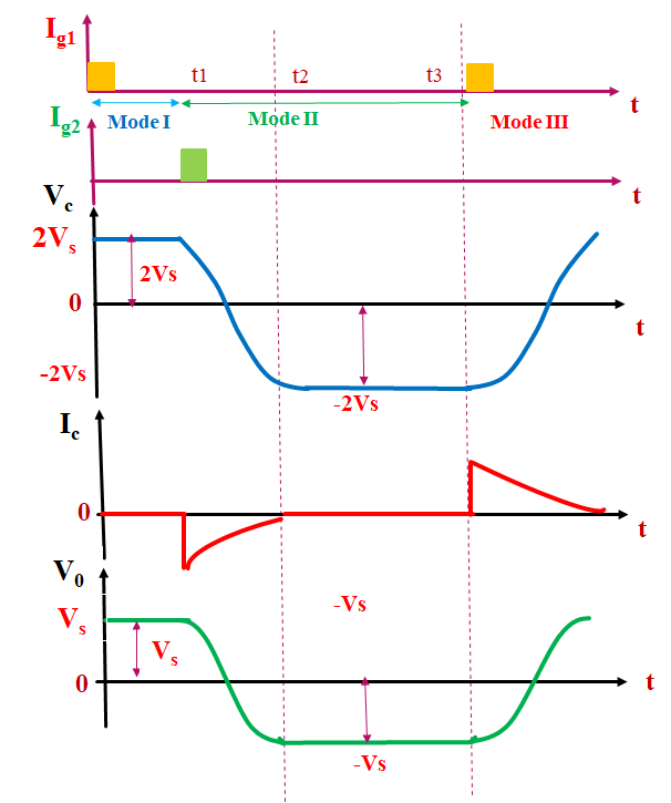
Now draw the waveform

Frequently Asked Questions (FAQ’s)
Why this circuit is called parallel inverter?
The inverter circuit in which the commutating component C (capacitor) is connected in parallel with the load via transformer called a parallel inverter. This circuit is also called Push-pull inverter.
What is the main difference between parallel inverter and series inverter?
One main difference between a series and a parallel inverter is that series inverters are connected one after another. Whereas, parallel converters are only connected individually. Second main difference between the two is that series inverters are used in small sub servers, whereas, parallel inverters are used in main servers.
what is series inverter?
The inverter circuit in which the commutating elements L and C are connected in series with the load to form an under damped circuit is called a series inverter. This circuit is also called load commutated or self-commutated inverter.