Looking for delta modulation (DM or ∆-modulation)?
In this article we explained all main and important points regarding Delta Modulation (DM) in detail.
let’s understand the topic:
like PCM (Pulse Code Modulation) and DPCM (Differential Pulse Code Modulation), Delta modulation (DM or Δ-modulation) is also a analog-to-digital modulation technique used for converting analog signals into digital format. It’s particularly suitable for signals with relatively slow variations.
In PCM , N-number of bit are transmitted per sample. Therefore, bandwidth requirement is very large. To overcome this problem we use delta modulation. In this scheme, only 1 bit is used to encode 1 voltage level thus, the technique allows to transmission only one bit per sample.
Read more: DPCM (Differential Pulse Code Modulation)
Table of Contents
Characteristics of delta modulation
It reduces the delivered data to a 1-bit data stream. It has the following characteristics:
- It is a simplified form of DPCM technique also known as 1-bit DPCM scheme.
- Here two sample values are compared, and result of this comparison is transmitted.
- Here input sequence is much higher than the Nyquist rate.
- It is simple to implement in both hardware and software compare other modulation scheme.
- Here quantization is simple, encoded signals which are over-sampled.
- Here, step-size is very small and fixed, i.e. Δ delta.
- It provides a staircase approximation of over-sampled base-band signal.
- Here bit rate can be decided by the user.
Operating Principle of delta modulation
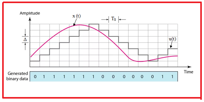
In delta modulation, present sample value X(nTs) is compared with previous approximated sampled value x^(nTs), and the result of this comparison is encoded and transmitted.
The compared value is called delta (Δ) value. The delta value is then compared to a predefined threshold or step size.
If present sample value X(nTs) is greater than previous approximated sampled value x^(nTs) then the step of the signal denoted by Δ is increased by 1. If present sample value X(nTs) is smaller than previous approximated sampled value x^(nTs) then step of the signal is decreased by 1 i.e., reduction in Δ.
mathematically,
X(nTs) > x^(nTs) +Δ i.e., increase in step size, then 1 is transmitted.
X(nTs) < x^(nTs) –Δ i.e., decrease in step size, 0 is transmitted.
Hence, delta modulation transmitted only one bit per sample.
Block Diagram of Delta Modulation
Let’s understand first the generation and detection of delta modulated signal.
Generation of delta modulated signal
The block diagram given bellow shows the generation of delta modulated signal:
Delta Modulator consist of a 1-bit quantizer and a delay circuit along with two comparator circuits.
The sampled signal x(nTs) and previous approximated sampled value x^(nTs) generated by accumulator circuit, is given to comparator circuit. The output of comparator circuit is an error signal ep(nTs) given by.
ep(nTs)=x(nTs)−xˆ(nTs)
This error signal ep(nTs) is given to the quantizer circuit. The quantizer quantizes the error signal ep(nTs). The quantizer generates the output in the form of steps. If positive magnitude pulse is provided to the quantizer as its input then quantizer performs increment by 1 step size, Δ.
It means that positive pulse at the output of the comparator circuit shows that message signal is greater than the arbitrary signal. Thus quantizer increases Δ by 1.
Similarly, If negative magnitude pulse is provided to the quantizer as its input then quantizer performs decrement by 1 step size, Δ. Thus, quantizer decreases Δ by 1.
The output of the quantizer at the same time, through a feedback path, is provided to the accumulator. An accumulator is nothing but a device that stores the signal for further operation. Thus, output of the accumulator is behaves like the second input of the comparator.
Finally, depending on the staircase signal if the step size is +Δ then binary 1 is transmitted and if it is –Δ then binary 0 is transmitted.
Detection of delta modulated signal
Detection of a delta modulated signal is very easy and is somewhat reverse of generation of a delta modulated signal.
It is a process of decoding the binary output of the delta modulator to reconstruct an approximation of the original analog signal. The goal is to reverse the encoding process and recover an estimate of the continuous analog signal from the binary data.
The block diagram given bellow shows the detection of delta modulated signal:
It consist of a accumulator circuit and LPF (low pass filter).
The accumulator consists of a comparator circuit and a delay unit. The transmitted signal along with the delayed signal is added at the comparator circuit.
If here the input is binary 1 then after a delay the output increased step size +Δ noticed. However, in the case of binary 0 as input, a decrease in step size is noticed. This generates the staircase signal equivalent to the message signal.
The output of the accumulator circuit is given to the LPF that smoothens the staircase signal to regenerate the original message signal.
Advantages of delta modulation
- It is relatively simple to implement.
- It has less components and computational requirements compared to Pulse Code Modulation (PCM).
- It has lower bit rate compared to PCM.
- It is particularly useful in telecommunications.
- It is well-suited for real-time applications, such as audio and video streaming.
- It permits low channel bandwidth as well as signaling rate due to transmission of 1 bit per sample.
Disadvantages of delta modulation
The main disadvantages of DM are
- Slope Over load distortion [occur when step size (Δ) is small]
- Granular noise [occur when step size (Δ) is large]
What is delta modulation?
Delta modulation is a digital modulation technique used to convert analog signals into digital format by encoding the difference (delta) between consecutive samples of the analog signal.
What is the purpose of delta modulation?
The main purpose of delta modulation is to efficiently represent analog signals with low bit rates, making it suitable for applications with limited bandwidth or storage capacity.
Read more: wiki
